Thanks to the tecnique which is used in L100 product
group, supports us to produce light-weight folding partitions
suspended from the top center with excellent
running properties. The folding panel stack can be
designed from 1,5 panels up to 6,5 panels which can
also be used as right and left hand installations. 1,5
folding panels may work without the need of bot-tom
guide channel but for folding panel stacks between
2,5 - 6,5 the bottom guide channel is necessary.
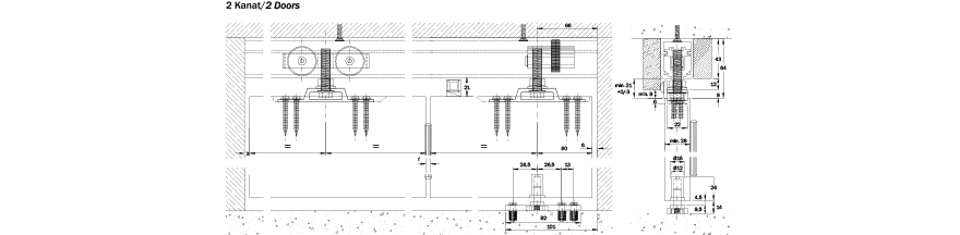
Specifications
• Easy assembly and adjustment
• Quite and effortless operation
• Height adjustment +0 / -3 mm
• Lateral adjustment
• Max. panel weight : 30 kg
• Max. panel width : 600 mm
• Max. panel height : 2400 mm
• Nr. of panel for folding stack: 1,5 - 6,5 panels
For light folding door applications, L30K and L30MK systems are advantageous
and practical systems that allow the doors to be fold either from the corner
and center with the same compounds. The logic under the system’s design
is that the folding panel partitions is solved simply, untroubled and economically.
However, because of the system’s being economical and efficient, it is
frequently used in visual areas. The wooden cover heights at the both sides of
the top track are not equal and thus the suspension hardware which are screwed
at the top of the door is seen from the side that panels folded and they
are caused an undesired sight. For that reason we recommend a secondary
application that is explained below for the places where visual demands and
economical solutions are looked for.
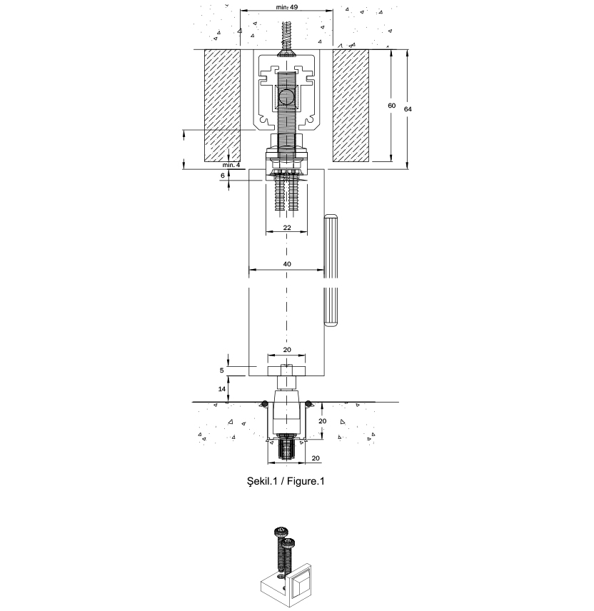
The stopper brackets (Figure.2) which are screwed at the top edge of the 1. 3.
5. doors are cancelled. The wooden covers are prepared as both have equal
heights and they are mounted 4 mm above of the doors as shown in Figure.1.
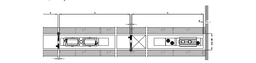
The distance between the covers must be min. 49 mm and they have to be
centered to the folding axis. In order to ensure the doors standing in straight
position when they are closed, a gap stave can be placed as shown in Figure.3
with the thickness equal to the “f” gap that is occured because of the hinge
that is used to connect the doors together.
* Approximate dimensions given
according to 600 mm door width
and 28 mm minimum door
thickness. It may differ accordng
to the hinge.
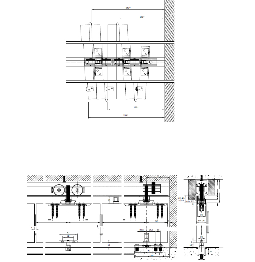
Nr. of hinges necessary.**
2 ad/pcs - 0-140 cm
3 ad/pcs - 140-210 cm
4 ad/pcs - 210-260 cm
Provided by customer.
** It may differ according to the capacity of load of the hinge.